ARC-32 Cabinet Support
Cabinet Configuration
Open the coin door under the control panel.
The Test and Service buttons panel is located to the left.
To install a game cartridge:
- Turn off the cabinet and unplug the power cable.
- Open the main service door under the control panel
- Put the door aside in a secure area.
- Locate the exA-Arcadia System and insert the game cartridge into an open slot.
Open the coin door under the control panel.
The volume knob is located to the left.
To change the A3 instructions in the Light Box:
- Turn off the cabinet and unplug the power cable.
- Pull the cabinet out
- Remove the screws from both sides of the Light Box.
- Carefully lift the back cover of the Light Box and disconnect the power connector.
- Remove the nuts from the inner side of the Light Box.
- Take off the Light Box.
- On a stable surface, remove the screws from the front of the Light Box.
- Swap the A3 instructions.
*Refer to the cabinet manual for more details.
To change the marquee/title panel:
- Turn off the cabinet and unplug the power cable.
- Pull the cabinet out
- Remove the screws from the top section under the Light Box.
- Carefully remove the panel and disconnect the fans connector.
- Place the panel in a secure area.
- Remove the bracket holding the ARC-32 panel and remove it from the slot.
- Place the marquee/title panel in front of it and insert it back into the slot.
- Secure the bracket with the screws.
- Reattach the fan harness.
*Refer to the cabinet manual for more details.
Installing an instruction strip:
- Open the control panel by unlocking it from the underside.
- Raise the front part of the control panel.
- Remove the screws securing the back part of the control panel.
- Lift the back part of the control panel.
- Remove the nuts holding in the instruction strip bar.
- Insert the instruction strip in the center.
- Reattach the instruction strip bar.
- Adjust the positioning as needed using the holes in the bar.
- Fully secure the instruction strip bar nuts.
*Refer to the cabinet manual for more details.
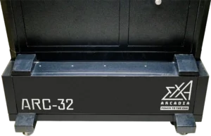
Stand
With 2 persons, carefully lift the cabinet on the stand.
Line up the holes so the cabinet casters are inserted into the stand.
Secure the cabinet with screws on the left and rights sides of the stand.
Monitor
To rotate the monitor:
- Turn off the cabinet and unplug the power cable.
- Pull the cabinet out and open the back door by unlocking it.
- Put the door aside in a secure area.
- On the back side of the monitor, remove the screws securing the monitor on the bracket.
- Gently pull out the monitor and rotate it 90 degrees in the desired direection.
- Place the monitor back in the cabinet and reattach the HDMI and power cables.
*Ensure to set DIP1 on the exA-Arcadia System for the correct monitor orientation.
Control Panel
Joysticks
- Open the control panel by unlocking it from the underside.
- Raise the control panel.
- Remove the screws from the joystick bracket.
- Remove the JST NH connector from the side of the joystick.
- Using a flathead screwdriver, place it against the bottom of the joystick base and remove the joystick ball.
- Put the replacement joystick's shaft through the control panel hole and secure it to the bracket with screws.
- Using a flathead screwdriver, place it against the bottom of the joystick base and screw in the joystick ball.
- Attach the JST NH connector.
※Only Sanwa joysticks which use the JLF-P-1 mounting bracket such as the JLF-TP-8T-SK model are compatible with the ARC-32.
※Only Seimitsu joysticks which use the SS mounting bracket such as the LS-32-01-SS model are compatible with the ARC-32.
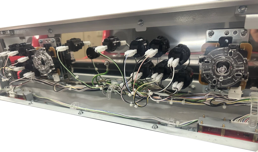
Buttons
- Open the control panel by unlocking it from the underside.
- Raise the control panel.
- Remove the 2 cables from the buttons.
- Push in the 2 buttons tabs from the underside of the control panel and push the whole button upwards.
- Position the replacement button above the whole and push down until it is secure.
- Attach the 2 cables to the button.
To install the 4 player control panel:
- With 2 persons, lift the 4 player control panel and place it into position to be secured to the cabinet.
- Ensure the 4 player control panel is unlocked.
- Attach the 3 bolts into the cabinet base to secure the control panel in place.
- Additionally, attach all secondary screws.
- Connect all wiring harnesses to both I/O boards.
- Close the back side of the control panel.
- Insert the carriage bolts on the top side of the control panel.
Payment Devices
To change the currency type in the coin mech:
- Open the service panel under the control panel.
- Remove the orange plastic coin in the comparator compartment.
- Replace it with the desired coin in your currency.
- Close the service panel.
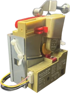
To install a payment card reader:
- Turn off the cabinet and unplug the power cable.
- Pull the cabinet out and open the control panel by unlocking it from the underside.
- Fully open up the control panel.
- Remove the coin guide component mounted on the back of the control panel.
- Mount the card reader where the coin guide was and run the required wiring harness to the bottom cabinet area.
- Open the coin and main service door.
- Connect the pulse signal wiring to the coin mech connector as needed
- Plug in the card reader's AC adaptor into the power strip in the main service area.
*For further guidance, refer to the card reader's manufacturer manual.
Moving the Cabinet
Turn off the cabinet and unplug the power cable.
At the bottom of the cabinet, turn both levelers counter clockwise until they are sufficiently above the casters.
The cabinet can now be easily pushed across flat surfaces.
*For narrow passages, the control panel can be configured into a vertical orientation. For 4 player control panels, it should not be configured into vertical orientation. Refer to the cabinet manual for further guidance.
DIP Switch Settings

ON = Vertical Monitor Orientation
OFF = Horizontal Monitor Orientation
*Note that all Vertical games also support Horizontal orientation. Only some Horizontal titles support Vertical orientation.
ON = Force 480p SD Resolution Output
OFF = HD Resolution Video Output
*For CRT monitor usage, a separately purchased HDMI to VGA DAC (Digital Analog Converter) is required.
ON = Rotate the Video Output by 180 degrees
OFF = Non-rotated Video Output
*Note that this feature is only compatible with some game titles.
Not Used
System Error Codes
Cause
The exA-Arcadia System cannot get a response from or is not correctly connected to a compatible JVS I/O Board.
Resolution
Ensure that the USB Type A to Type B cable used is a fully wired high quality cable and not a cable built for charging.
Compatible JVS' I/O Boards
*These models are not compatible with the JVS protocol.
Troubleshooting for multiple cabinet configurations
All linked cabinets must be turned on simultaneously with the exA-Arcadia System.
The exA-Arcadia system boots quickly. All cabinets and correspending I/O Boards must provide a response to the system during initialization or an I/O Error message will be displayed. It is highly recommended to only install JVS' I/O Boards for multiple cabinet installations. Standard JVS I/O Boards do not robustly support linked cabinets.
*Note that for older system models using standard JVS I/O Boards, the maximum supported length of USB cables is 5 meters between daisy chained I/O Boards. On newer system models using JVS' I/O Boards, the maximum supported length of USB cables is 30 meters between daisy chained I/O Boards.
Cause
The game cartridge cannot be read or is not functioning correctly.
Resolution
Try gently cleaning the cartridge edge connector with a Q-tip and using canned air, blow out dust that may be in the cartridge slot.
For any further help, send a service request via our Contact Form.
Cause
A game cartridge was removed from the exA-Arcadia System while it was on.
Resolution
Do not hot swap, insert or remove game cartridges while the system is turned on.
Cause
The exA-Arcadia System's bookkeeping calendar data is out of sync.
This can occur from repeated power cycling of the system over a short period of time or a dead calendar battery.
Resolution
For the newer style exA-Arcadia system
Locate the battery on the outside of the system below the left cartridge slots. Carefully
remove the battery by lifting up from the right side taking care not to use excessive force and avoid bending the holder pins on the left side.
Replace the battery with a high quality brand CR2032 battery by inserting under the pins on the lefthand side and pushing down on the righthand side.
Do not push the battery in over the pins on the lefthand side as this can cause damage to the system.
To reset the bookkeeping calendar data, allow the system to run for a few hours without a game cartridge inserted.

For the older style exA-Arcadia system
Send a service request via our Contact Form.
Cause
The exA-Arcadia System's bookkeeping calendar battery is running low.
Resolution
For the newer style exA-Arcadia system
Locate the battery on the outside of the system below the left cartridge slots. Carefully
remove the battery by lifting up from the right side taking care not to use excessive force and avoid bending the holder pins on the left side.
Replace the battery with a high quality brand CR2032 battery by inserting under the pins on the left-hand side and pushing down on the right-hand side.
Do not push the battery in over the pins on the left-hand side as this can cause damage to the system.
To reset the bookkeeping calendar data, allow the system to run for a few hours without a game cartridge inserted.
For the older style exA-Arcadia system
Send a service request via our Contact Form.
For long text based error messages, send a service request via our Contact Form detailing the error message.
Still having issues?
Get in touch with our customer support team for more help. Provide the serial # for each product in your request for the quickest service.
Contact Support